
 ChatGPT
 Claude
 Perplexity
 Grok
 Gemini
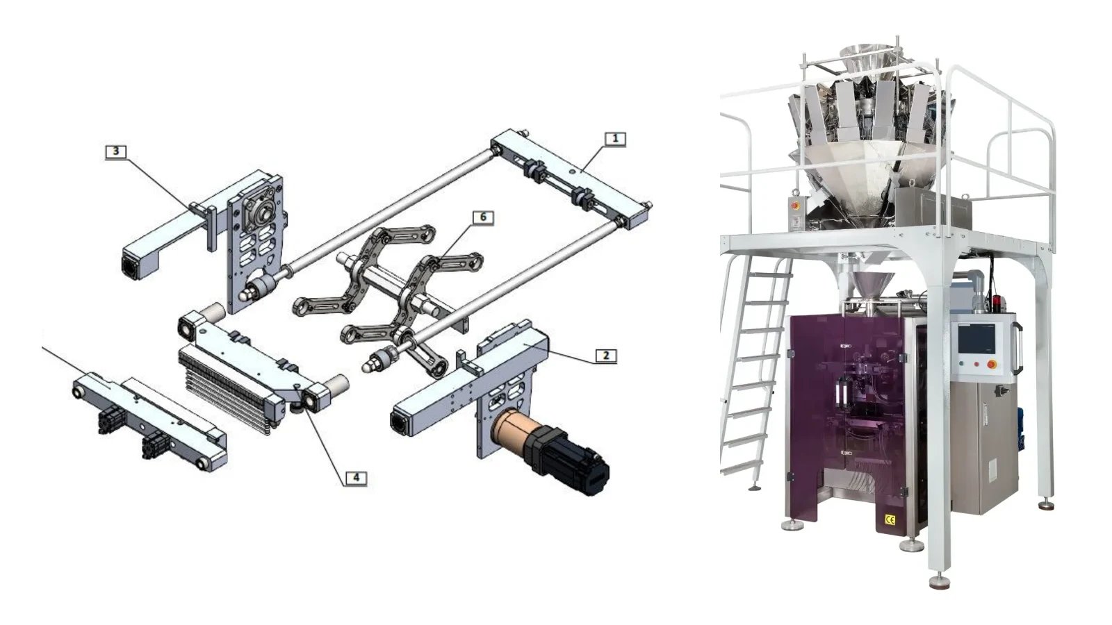
A fly jaw is the sealing system of a continuous-motion vertical packaging machine (VFFS): the horizontal sealing jaws travel with the film and close while it moves, so the film never stops for sealing. Continuous motion can lift output from the 60–80 packs per minute typical of intermittent machines into the 120–200 packs per minute range. The TAMTAŞ CMP 444 combines a lightweight jaw body, a timing-belt servo drive and a spring damping mechanism to run at up to 180 packs per minute. The system dynamics were analysed with a digital twin built in MSC ADAMS and validated against sensor data from the real machine.
Key takeaways:
- The film runs without stopping; the jaw opens and closes in sync with film speed.
- A servo motor, a 1/20 planetary gearbox and a crank-rod chain drive the jaw.
- Die springs with a stiffness of k = 388 N/mm damp impact energy and ensure even sealing pressure.
- An electronic cam (E-Cam) profile with a third harmonic creates a short dwell while the jaws are closed.
- The ADAMS model predicted 1.4 N·m motor torque; 1.1 N·m was measured on the real machine.
Intermittent vs continuous-motion vertical packaging
Vertical packaging machines are the industry standard for powders and granules: film forming, product filling and sealing take place in a single unit. Machine performance is defined by the horizontal jaw, the vertical jaw and the forming tube, while seal quality depends on temperature, pressure and dwell time.
On intermittent machines the film stops completely during sealing. The stop-and-go inertia of every cycle limits output, typically to 60–80 packs per minute. On continuous-motion machines the film moves without interruption and the horizontal jaw opens and closes in sync with the film feed. This architecture removes stop-and-go inertia and enables 120–200 packs per minute and above. The trade-off is that servo synchronization and jaw drive design become critical engineering challenges.
What is the fly jaw concept?
In the fly jaw concept the jaw assembly moves continuously in sync with the film feed, and the opening-closing cycle runs without stopping the machine. This requires the moving mass to be kept as low as possible. On the CMP 444 the jaw body was therefore lightened with pockets and cut-outs while keeping its rigidity, and surface transitions and corner radii were optimized to avoid stress concentration at high speed.
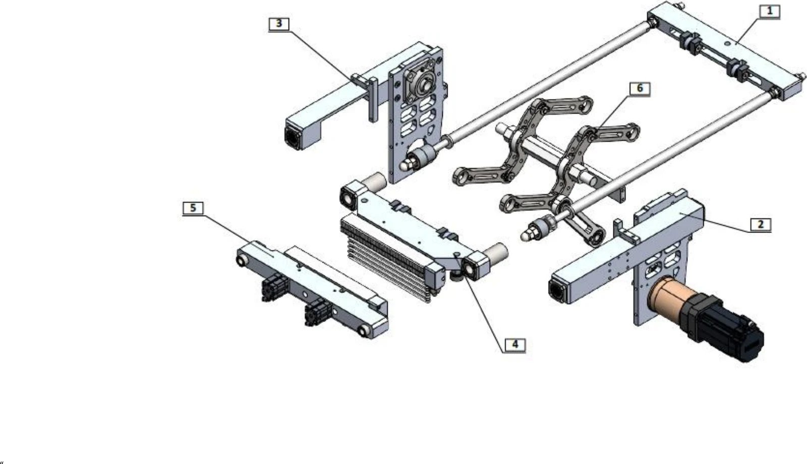
The drive chain works as follows: the servo motor turns the crank arm through a helical planetary gearbox with a 1/20 ratio. Connecting rods transfer this motion to an intermediate shaft and from there to the push rods attached to the jaw. This multi-link kinematic chain converts the motor's rotation into a linear closing force on the jaws. Double-row bearings at the joints reduce friction losses, and an inductive sensor reports the jaw position to the control system in real time.
Front and rear sealing jaws
- Front sealing jaw: A passive anvil with no pneumatic cylinder or blade. Together with the rear jaw it compresses and heats the film, using two 220 V / 300 W heaters and a J-type thermocouple for even heating.
- Rear sealing and cutting jaw: The active surface in direct contact with the film. Its temperature is controlled by two 220 V / 300 W heaters and a J-type thermocouple. A 280 mm HSS blade that separates the packs is driven by two compact pneumatic cylinders.
Spring damping: absorbing impact, returning energy
The closing force between the two jaw bodies is transmitted through guide shafts on both sides. Heavy-duty die springs with a 32 mm outer diameter are fitted in pairs on each shaft, with a measured stiffness of k = 388 N/mm and a preload of 388 N. The preload takes up the clearances in the mechanism before the jaw starts to move, so the film is compressed evenly and seal quality is maintained at high speed.
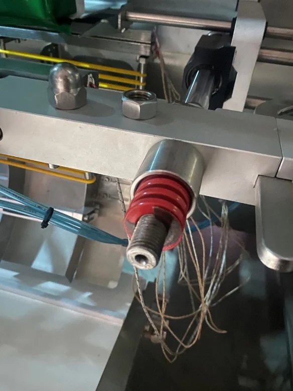
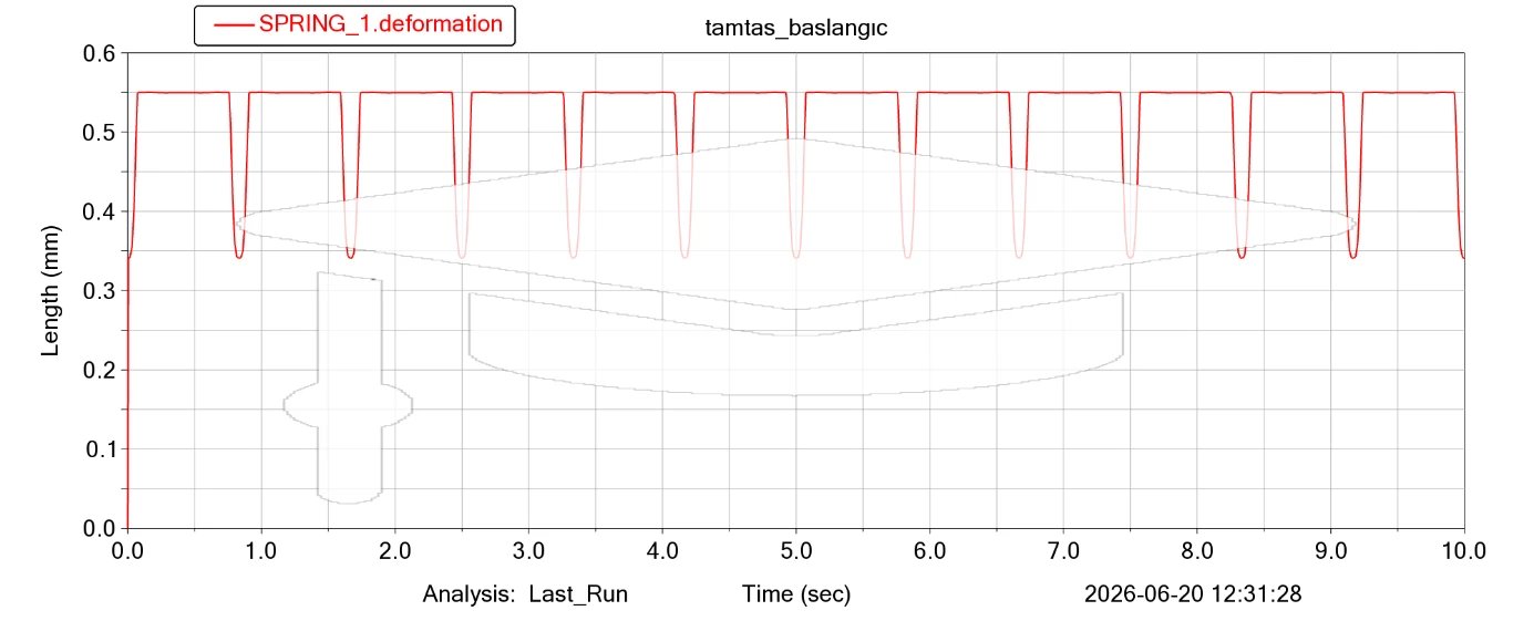
A damping ratio of ζ = 0.3 was chosen: a deliberately underdamped design that absorbs the impact energy of jaw closing quickly without excessive oscillation. The natural frequency of the spring-mass system is about 39.8 Hz; with a 1.2 Hz operating frequency the frequency ratio is 0.03, so there is no risk of resonance.
In the simulation the spring compresses by about 0.65 mm in each cycle and fully recovers. For a spring with a 38 mm free length this is only 1.7% compression. The spring returns the elastic energy stored at closing back to the system during opening, which lowers the torque peaks seen by the servo motor and extends the life of the drive train.
The electronic cam (E-Cam) motion profile
On the real machine the jaw is driven by the servo motor's electronic cam profile. To reproduce this behaviour in simulation, a Fourier series with a third harmonic added to the fundamental frequency was used instead of a plain sine:
θ(t) = 35.39° − 39.814° · cos(2π · 1.2 · t) + 4.424° · cos(2π · 3.6 · t)
The equation has three practical effects:
- Full stroke: The crankshaft oscillates between 0° and 70.78° with no correction function needed. The operating frequency was set to 1.2 Hz based on the real machine's speed profile.
- Dwell zone: The 3.6 Hz third harmonic flattens the acceleration curve while the jaws are fully closed. A short dwell forms, so the mechanism does not suddenly reverse while the product is compressed and sealed, and impact loads drop.
- Smooth start: Angular velocity is zero at t = 0. Sudden speed changes and jerk are avoided without extra ramps or filters.
Validation with an ADAMS digital twin
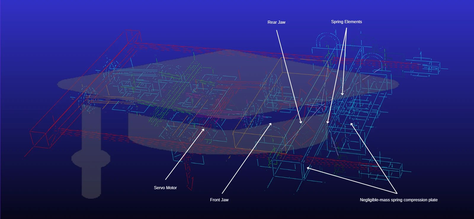
The system was modelled in MSC ADAMS as a closed-loop multibody model. Mass, centre of gravity and inertia values came from SolidWorks mass properties, and the contact between the jaws was defined with a metal-to-metal impact model.
The results were compared with sensor data from the real machine:
- Velocity profile: The angular velocity from the simulation and the jaw velocity signal from the machine showed regular oscillation with the same period and waveform. This qualitative match shows that the mass-based model represents the system kinematics correctly.
- Motor torque: ADAMS predicted a peak of 1.4 N·m at the motor shaft, while 1.1 N·m was measured on the real machine. The model captures about 79% of the real load and gives a worst-case upper bound, which makes it a reliable preliminary design tool for motor and gearbox selection.
The lower, smoother torque curve on the real machine is explained by the flexibility of the power transmission components and by the servo drive algorithms filtering out sudden acceleration shocks.
What this design brings to a production line
- Higher output: with no stop-and-go inertia, the CMP 444 runs at up to 180 packs per minute.
- Consistent seal quality: Spring preload and the dwell zone provide even compression even at high speed.
- Longer drive life: Spring damping reduces torque peaks reaching the servo motor and drive train.
- Flexible speed settings: The E-Cam profile can be re-tuned for different speed settings.
Background of the study
This article is based on the paper "Energy-Efficient High-Speed Moving Jaw Design for Continuous-Motion Vertical Packaging Machines and ADAMS-Based Dynamic Validation", a joint study by Istanbul Technical University and TAMTAŞ. Its authors are Emre Serdar Gürsoy (ITU), Gökhan Mengütay and Erdoğan Türkoğlu (TAMTAŞ) and Prof. Dr. Mustafa Bakkal (ITU).
Frequently asked questions
How many packs per minute does a continuous-motion vertical packaging machine make?
The continuous-motion architecture removes the 60–80 packs per minute limit of intermittent machines and makes 120–200 packs per minute and above possible. The CMP 444 runs at up to 180 packs per minute; actual speed depends on the product, bag size and film type.
What is the difference between a fly jaw and a fixed jaw?
On a fixed-jaw (intermittent) machine the film stops for sealing. With a fly jaw, the jaw moves with the film and seals while it travels, so the film never stops. This removes the speed limit caused by inertia.
Why does the servo drive matter?
The servo motor keeps the jaw synchronized with film speed and, through the E-Cam profile, lets the speed, acceleration and dwell time of the motion be set in software. Switching between products and speed settings needs no mechanical change.
How do the springs affect seal quality?
Die springs preloaded to 388 N take up the clearances in the mechanism before the jaws close and create even pressure on the film. They also damp the closing impact, helping to maintain seal quality at high speed.
Take a closer look at the CMP 444
For technical specifications and applications, see the CMP 444 continuous-motion vertical packaging machine page. Use the machine selector to find the right machine for your product, or reach our team through the quote form with your capacity target.